.
The gap on the tube is set to say 1/32, when the
discharge takes place the cold electricity sent out through the grids to the
storage battery, and you are charging the storage battery for free. And you did not close the loop to short it out.
Gray was too close to providing the world with free energy with just an
antenna of any kind ,,,,,, SO THEY KILLED HIM.
So we have the Swiss (Linden Experiment) machine that works the same way, we have Gray's
Machine, and we have the car that Tesla built that
works the same way, They all use the same (Principle as the) tube just different variations.
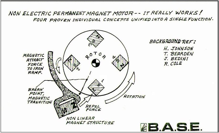
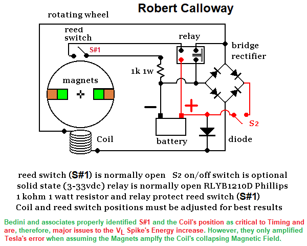
According to this Web Page's Author, the inspiring Primary Tesla premise was not only present in the Linden Experiment and Gray's Machine, reflected in both Kromrey's Generator and the Bedini North Pole Motor/Generator (or School Girl Motor), boldly declaring and demonstrating Tesla's thesis; that there is, initially, a higher AVERAGE Electron Voltage Energy present in any controlled repetitive level of an Inductive Reactance's Transient Phases' Spikes (see the Spike hz 'Electron' Pump on these Web Pages). Tesla's sparks were actually VL's Spikes. The higher level Voltage of Lightning originates as two dissimilar Elements' and/or Two frequencies Impulses are interacting to form an isolated, Battery like, Charges within the Diode Effect. The "Transient Phase" occurs when a conducting non-Magnetic material is subjected to the cycling Transient Phases' higher Instantaneous Voltage Transformation Potential Differences and, thereby, these Timed, repetitive Inductive Reactance's Transient Phases induce (amplify or accelerate) a commensurately higher Average number of Electrons (see Figs. 24, Wave Clarity in this Web Page's section titled, Intro to My Very Interactive Transient Phase Simulation ). A Transient Phase's dynamic, low Voltage Inductive Transformation is reflected in Copper's (non-Magnetic) response to maintain an Electron Density equilibrium as Electrons are being compressed in cyclical Transient Phases controlled by Switch #1 ... and, wallah, what exists when a circuit has been designed to accommodate each requirement of a successful higher Potential Difference Density Intensity of Electrons?
You can make this anyway you want to experiment with. I used this as a medical machine with light currents for treatment with one electrode.
Good going Robert, Have fun. - John
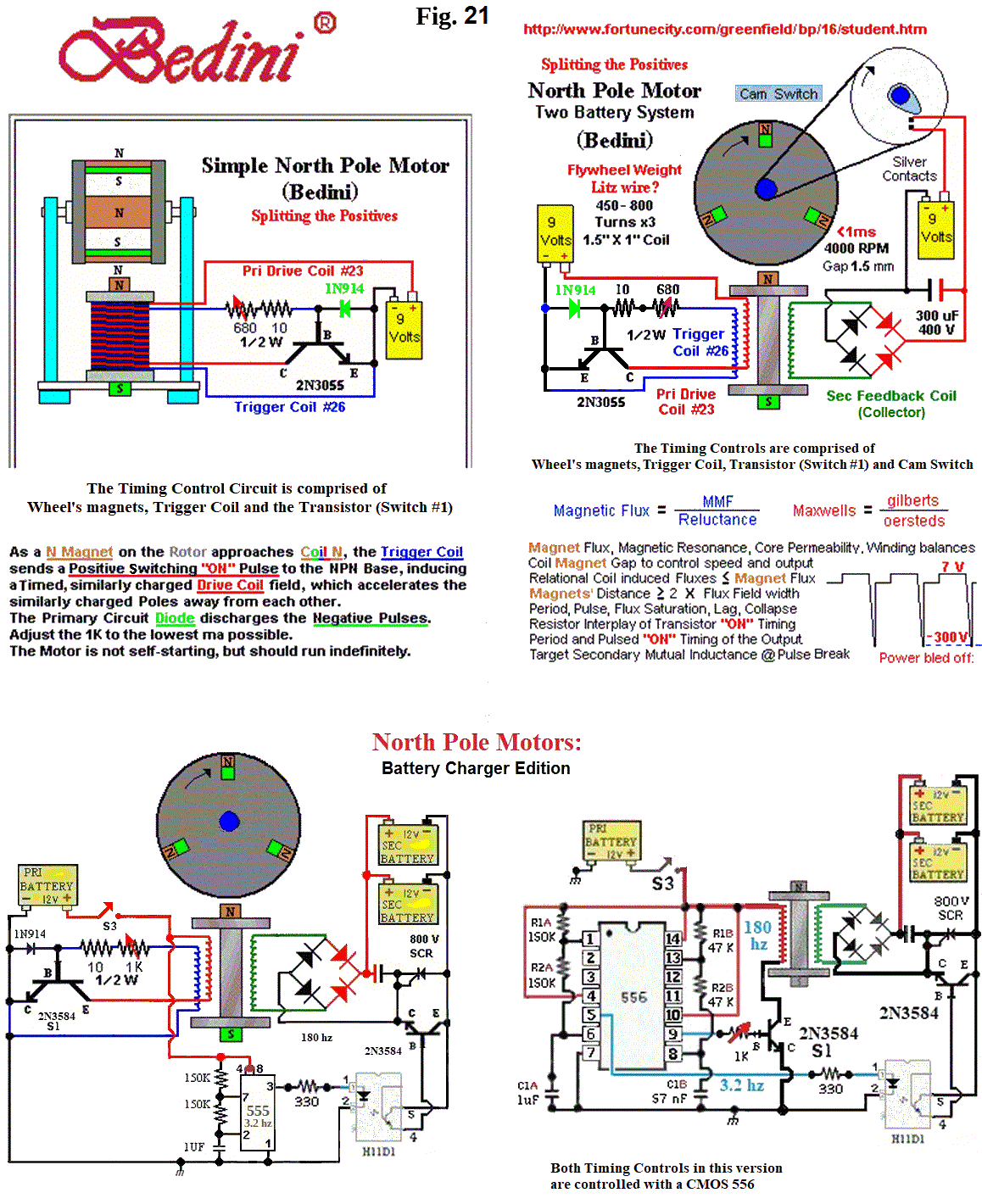
Try this experiment, take three flashlight
batteries and put two on one side in series and one on the other side, then connect the
two negatives together, now between the two + poles connect a light,.. this is
splitting the positives,
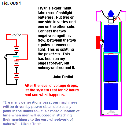
This has been on my pages forever, but nobody understood it.
Jerry please this for the group.
This Web Page's Author has actually seen and read several Patents (Kromrey, Bedini, etc) that were literal attempts to replicate Tesla's achievement. My research (which is shared on these Web Pages) has discovered, (or rediscovered ... depending on interpretations of how much Tesla did know), not only what Kromrey, Bedini and others missed in recreating Tesla's apex achievement, but I comprehend the biggest challenge for Tesla and all who attempted to replicate Tesla's achievement was controlling an Energy for which they did not understand its origins. They have had partial formulas for nearly 100 years, yet, I now know where the Impulse Energy originates and also have the formulas to control the process. I have created 2 million Volts from 2 Volts.....
Subject: Re: [Keelynet] Re: Lindemann on the World of Free Energy
Date: Tue, 5 Jun
2001 00:51:16
-0700
From: john1
To: Jerry W. Decker
Jerry - You do what you want with the picture, this tube is very hard to
make. It requires a milling machine
to do it and, no, it's not my version, it's Gray’s tube. This is what was hidden
inside of the Swiss machine and what Tesla and. Gray also used/ I will send you the lab
notes, but I'm sure Peter will give them to you.
Robert is the one, He did real good
in the answer. The tube if you want these tubes
are about 3" in diameter grid spacing is 1/4 " between grids 5" long 1/4 inch
brass rods with silver gaps.
email John
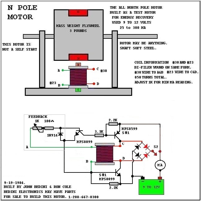
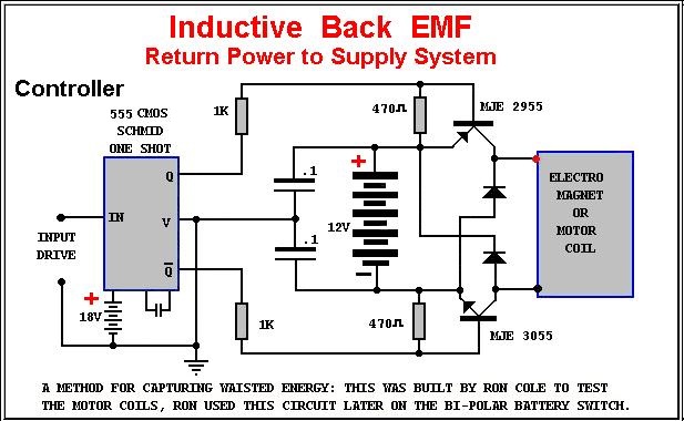
Bedini
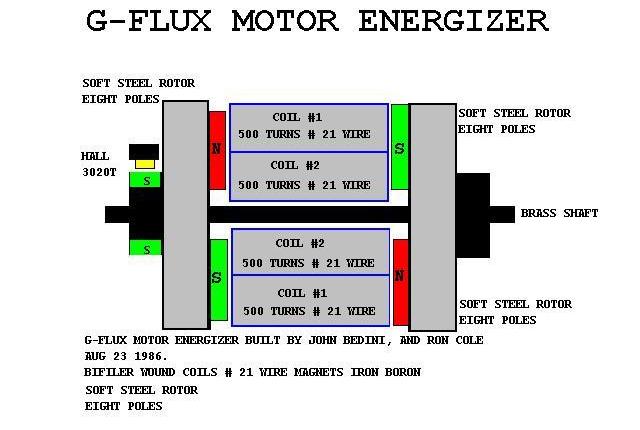
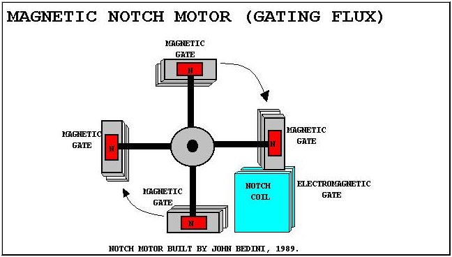
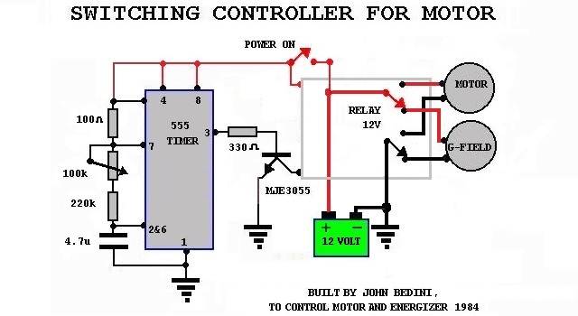
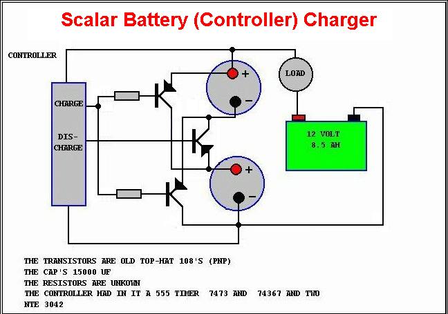
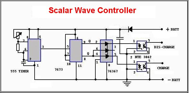
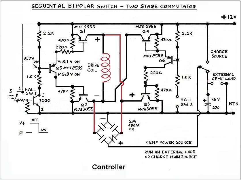
Experiments
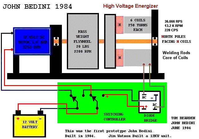
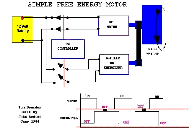
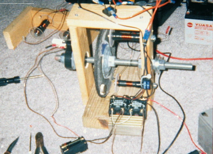
with a Kromrey and Brandt converter built by John Bedini
John
Bedini energy machine pictures
The
Tesla switch
Either any of my Transient Phase Simulations or the CircuitMaker Program are using Excel
(or Spreadsheet type techniques) for their intense calculations.
It is, therefore, advisable and wise to know Three things:
Any of these resources files can be corrupted if your
computer's resources are over-taxed.
and a requirement to use any of the Transient Phase Simulations is to have Excel or an equivalent.
Preserve Original File, and Work only from a backup to avoid File corruption when using these resources, and be vigilant protecting your work.